AVR gives us 32-8bit “General Purpose Working Registers” for all our calculating needs. There are a couple nuances and peculiarities to these registers that are worthy of noting.
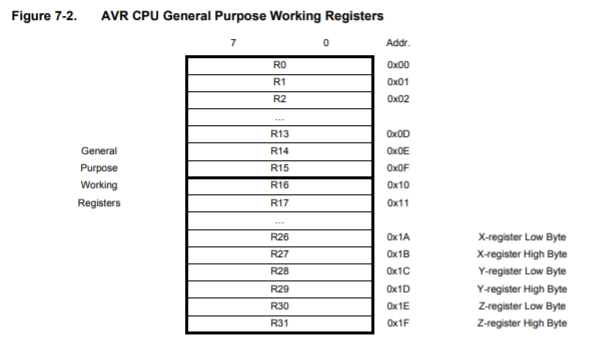
Right off the bat, we can see that Registers 26 through 31 are special. These registers will be used for holding 16 bit addresses, and function as pointers. m328pdef.inc defines them as such…
; ***** CPU REGISTER DEFINITIONS *****************************************
.def	XL	= r26
.def	XH	= r27
.def	YL	= r28
.def	YH	= r29
.def	ZL	= r30
.def	ZH	= r31
However, you can simply use X, Y, or Z to refer to their respective register pair…
//there are only 3 word based instructions
movw X,Y ;move word value in XH:XL to YH:YL
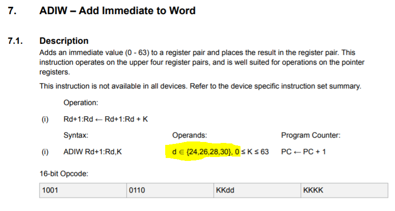
adiw X,1 ;add immediate to word XH:XL
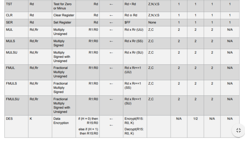
sbiw Y,1 ;sub immediate from word YH:YLMost of the datasheets seem to use the ordering XH:XL to describe register pairs. Such as when describing the destination of the MUL instruction, “R1:R0”, in the instruction set manual…
…though, there is no reason it needs to be this way. The following instructions will all do the same thing, and will all be valid….
movw XH:XL,YH:YL             ;pairing order
movw XL:XH,YL:YH             ;doesn't matter
movw XL:XH,YH:YL
movw XL,YL                   ;you don't even need it
movw XL,YL:YH                ;it's totally optional
movw XL,YH:YL
movw XL:XH,YL
…got the point? No? The following instructions will NOT be valid…
movw XH:XL,YH
movw XL:XH,YH
movw XH,YH
movw XH,YL:YH
movw XH,YH:YL
…got it? Register pair notation is optional. If you simply supply the lower register as an argument to the instruction, it will assume the location of the upper register. This should be a subtle hint that we cannot customize our register pairs; and definitely CANNOT swap register pairs by doing this. And finally, we CANNOT supply the upper registers only as arguments. In fact, you can’t even use the movw instruction with a word that starts on an odd numbered register at all! The following instructions are not valid…
movw r1,r3         ;can't use odd word boundaries
movw r1,r4         ;can't use odd word boundary for destination
movw r4,r1         ;can't read from odd word boundary either
….thus, we seem to have a barely visible word boundary in our Register Space. That’s kind of a bummer, but the upside is that the movw instruction is the only one of the 3 word based instructions that will operate on ANY of the General Purpose Working Registers(so long as it starts on an even numbered register of course).
movw r0,r2        ;valid
movw r16,r0       ;valid
movw r24,r26      ;valid
The other 2 word based instructions are Add Immediate to Word(ADIW) and Subtract Immediate from Word(SBIW), and they work only with the X, Y, and Z register pairs. But, wait… there is another! This isn’t well documented, but Registers 24 and 25 can also be used as a register pair with the ADIW and SBIW instructions. This kind of makes it like the X, Y, and Z register pairs, so sometimes I refer to it as the W register. This name is fitting, because even though it cannot be used as a pointer like X, Y, and Z, it can be thought of as a Word Register. This little easter egg seems to only be noted twice, once in the ADIW description and once in the SBIW description, making it a very elusive feature.
That’s enough about Register Pairs. On to Registers 0 through 23…
You’ll notice that bold line dividing R0 through R15 from the rest of the registers. R0 through R15 are very particular in that they cannot have values Loaded Immediately(LDI) into them. They will not Subtract Immediates(SUBI,SBCI), they will not And w/ Immediates(ANDI), they will not Or w/ Immediates(ORI), and they will not Compare w/ Immediates(CPI). Short of those not working with those 6 instructions, R0-R15 can be treated almost like any other General Purpose Working Register.
But that’s not all! Registers R0-R15 are actually used for some built in functionality as well. This should be important to know, because I often see people assume that R0 is always zero, so they end up using it as a “Zero Register”. I worry this could be bad practice, because if you had recently used any of the 6 Multiply Instructions, then their result might be left over in R1:R0. The 6 Multiply Instructions: MUL, MULS, MULSU, FMUL, FMULS, FMULSU all place a result into the register pair R1:R0. And as far as I know, it is not cleared automatically. The Load Program Memory(LPM) instruction also, by default, loads the byte pointed to by Z into R0, unless a specific destination register is otherwise specified…
LPM Z           ;loads byte into r0
LPM tmp,Z       ;loads byte into tmp
The only other built in functionality I have found that demands use of R0 through R15 is the Data Encryption Standard(DES) instruction; which is not standard in all AVR devices. This is a cryptographic instruction that essentially takes 8 bytes of data and encrypts it using 8 other bytes as a key. DES takes no arguments when written, but expects the 8 bytes of data to encrypt/decrypt to be in R0,R1,R2,R3,R4,R5,R6,R7, and it expects the 8 bytes used for the key to be in R8,R9,R10,R11,R12,R13,R14,R15. Some AVR devices feature AES, but it is implemented as a peripheral module, and doesn’t need the General Purpose Working Registers.
Registers R16 through R23 are the registers that are most available for quick calculating. They don’t have any special functionality and are thus about as General Purpose as a Working Register can get.
