High level languages seem infinitely complex, and impossible to master; with endless libraries, written by tons of people. But I find some Assembly languages, particularly AVR, to be nice and concise with a digestibly sized instruction set that fits in a single 191 page pdf. I am actually struggling to learn C at the moment; because honestly, C trying to emulate all the functions of AVR Assembler just ends up being more confusing syntactically than the original Assembly. Anyway, here is a generic 16-bit template for AVR Assembler. I say 16-bit, because it is structured to be useful for 16-bit calculations. It takes advantage of some preprocessor tricks that help make 8-bit registers behave like 16-bit registers. It is mine, and much better for me than the AtmelStudio Assembler template, which I think just increments r16 indefinitely. I will give some basic introduction to the AVR Assembly concepts and tricks that make this useful for starting up a small 16-bit Assembly Program.
//DEPENDENCIES////////////////////////////////////
.include "macros.asm"

//REGISTER DEFINITIONS////////////////////////////
.def ac   = r16 .def acL   = r16 .def acH   = r17  ;accumulator
.def bc   = r18 .def bcL   = r18 .def bcH   = r19  ;b-cumulator
.def tmp  = r20 .def tmpL  = r20 .def tmpH  = r21  ;temp-regs
.def tmp2 = r22 .def tmp2L = r22 .def tmp2H = r23  ;temp-regs

//DATA ALLOCATION SEGMENT////////////////////////
.DSEG
     datacopy:  .byte strlen("All that is gold does not glitter")+1
     variableA: .byte 2
     variableB: .byte 1

//CODE SEGMENT///////////////////////////////////
.EQU RESET     = 0x0000 ;program always starts here
.EQU CONSTANTS = 0x0800 ;address to store constants
.EQU MAIN      = 0x0100 ;address to store program
.CSEG .org CONSTANTS
    constantdata: .db "All that is gold does not glitter",0

.org RESET
    rjmp MAIN

//MAIN PROGRAM/////////
.org MAIN
	COPYSTRINGPGM ramcopy,romdata

        //WRITE PROGRAM HERE....

	endloop:
		nop
		rjmp endloop
//PLACE SUBROUTINES HERE/////////////////////

.exit ///////////////////////////////////////
//NOTES//////////////////////////////////////

/////////////////////////////////////////////
.macro LDZPGM
ldi ZL,low(@0)
ldi ZH,high(@0)
lsl ZL
rol ZH
.endmacro
.macro LDY
ldi yl, low(@0)
ldi yh,high(@0)
.endmacro
.macro COPYSTRINGPGM
LDZPGM @1
LDY @0
LPM tmp,Z+
ST Y+, tmp
CPI tmp,0
BRNE PC-3
.endmacro
Okay, so let me explain. Starting at the top and working our way down slowly…
Because I like to keep all of my macros in a separate file from the get-go, I need to include it with the directive .INCLUDE. File formats can be .asm, .s, or .inc. I placed this directive at the top because Macros must be declared BEFORE any potential use; but really, the Include directive can be placed just about anywhere, and the assembler will essentially insert the entire document into the line where it was included. I could very well include documents at the bottom or even in the middle of the main document.
In the case of ATmega328p, the file “m328pdef.inc” will already be included by default as a dependency from when I tell AtmelStudio which device I wish to code for. I treat it like a third document in my program. It is where I can find all of the default device Constants(.equ) such as peripheral addresses and some register definitions(ex: .def XL = r26 .def XH = r27). Here is a small snippet from m328pdef.inc that declares constants for some I/O Peripheral Registers.
; ***** I/O REGISTER DEFINITIONS *****************************************
; NOTE:
; Definitions marked "MEMORY MAPPED"are extended I/O ports
; and cannot be used with IN/OUT instructions
//only use ST/LD type instructions
.equ	UDR0	= 0xc6	; MEMORY MAPPED
.equ	UBRR0L	= 0xc4	; MEMORY MAPPED
.equ	UBRR0H	= 0xc5	; MEMORY MAPPED
.equ	UCSR0C	= 0xc2	; MEMORY MAPPED
In My Example Template, I defined(.def) my registers at the top because that is just traditionally where programmers tend to stick global things. But actually, I can define registers anywhere. If at any point in my code, I want to change the name of a register, I can undefine(.undef) the name, and re-define the register with a new one. Though I haven’t used .UNDEF in My Example Template, it is useful to mention.
I can define multiple names for a single register. This will prompt a warning from AtmelStudio, but not an error. I have found this is useful for extending 8 bit registers into 16 bit registers. In My Example Template, by defining Register 20 as both tmp and tmpL, I can use either name to refer to the same register. This is useful if I want to switch back and forth between using tmp as an 8 bit temporary variable or using tmp as a 16 bit temporary variable while keeping the names aesthetic and not having to constantly undefine and re-define them. Thus, the following will Assemble with a warning, but no error.
.def ac   = r16 .def acL   = r16 .def acH   = r17
.def bc   = r18 .def bcL   = r18 .def bcH   = r19
.def tmp  = r20 .def tmpL  = r20 .def tmpH  = r21
.def tmp2 = r22 .def tmp2L = r22 .def tmp2H = r23
Actually, to be honest, the main reason I desire to have some consistency in naming my Low and High registers when dealing with 16 bit values, is because of a neat grammar trick I have found when writing macros. AVR Assembler uses Parameterized Macros that can take registers as arguments. If I wanted to write a Macro to add two 16bit numbers, normally it would require 4 arguments..
.def acL = r16 .def acH = r17
.def bcL = r18 .def bcH = r19

//when writing macros arguments look like this @0, @1, @2, @3, etc
.macro ADDWORDS
    add @0,@2        ;add the low bytes
    adc @1,@3        ;add the high bytes w/ carry
.endmacro

//now call the macro
ADDWORDS acL,acH,bcL,bcH       ;takes 4 arguments
However, because of the way Macros work, and the way I have named my registers, I can totally rewrite this macro with only 2 arguments, and the following will Assemble without Error; and is much more aesthetic.
.def acL = r16 .def acH = r17
.def bcL = r18 .def bcH = r19

.macro ADDWORDS
    add @0L,@1L        ;add the low bytes
    adc @0H,@1H        ;add the high bytes w/ carry
.endmacro

ADDWORDS ac,bc
This works because macros are actually taking the names of the registers as arguments during pr-processing, not the registers themselves. So it essentially just copies and pastes “ac” where it sees @0, and “bc” where it sees “@1”. Thus I have hacked Macros to require less arguments; allowing for prettier code. Again, though I haven’t actually done this in my example code, I have found it pretty invaluable, and useful to know about.
Let’s talk about the macros I have written. I think my second macro, which loads the Y pointer will be the easiest to explain. Observe the comments…
.DSEG
    ramcopy: .byte 69   ;ramcopy expresses a 16bit address

.CSEG
.macro LDY              ;Macro loads Y pointer w/16bit address
    ldi YL, low(@0)     ;Load the Lower 8bits into Y
    ldi YH,high(@0)     ;Load the upper 8bits into Y
.endmacro

LDY ramcopy   ;Y will now point to ramcopy
I use .DSEG to declare an address in RAM. Labels always express an address, which can be loaded into registers as an immediate value. However, since no Load Immediate Word instruction seems to exist in the AVR Instruction Set, I have to use the built-in “functions“(which I think are just built in weirdly formatted macros): low() and high() to chop the 16 bit address into bytes. Those bytes can now be treated as immediate values for loading or whatever.
Loading the Z register is a little different however, because I am going to use it to point to Program Space, where as I was using Y to point to RAM or Data Space.
.CSEG
    constantdata: .db 69  ;.db stores a constant in Program Space

.macro LDZPGM
    ldi ZL,low(@0)  ;load the low
    ldi ZH,high(@0) ;load the high
    lsl ZL          ;use logical shift to avoid carries
    rol ZH          ;use rol to use carries
.endmacro

LDZPGM constantdata
Okay, so my comments explained nothing. I will explain this more later when I talk about the .ORG directive, but Data Space(RAM) and Program Space(ROM/FLASH) are organized differently, that is to say they use different addressing schemes. While Data Space maps a byte to every address, Program Space maps a Word to every address. For Z to point correctly it must be multiplied by 2. This is achieved in Assembly by Logically Shifting a register to the left by one place. Because I am dealing with a 16bit number and 8 bit registers I have to shift both the low and the high registers. This is where my comments will make sense. Both the Logical Shift Left(lsl) and the Roll Left(rol) instructions shift bits one place to the left, but they do it slightly differently. If a bit is lost while shifting a register, it actually is said to go into the Carry Bit. The bit that is gained is where these two instructions differ. Rolling uses the Carry Bit to fill the vacancy left by the shift, where as Logically Shifting will always just leave vacancies as zero. If you visualize it like this…
High Reg 0000 0000 Low Reg 0000 0000
Carry Bit 0
Shifting Left <———- <— <————–
…it becomes more obvious that I have to shift the Low Reg first, because it might generate a Carry. If it does, I want that bit to be loaded into the vacancy of the High Reg when I shift it. However, I DON’T want anything going into the vacancy left over by shifting the Low Reg.
Having to use two different instructions on High vs Low Registers when trying to do 16-bit AVR is common across most arithmetic operations; even simple adding. You usually must use the ADD instructions for the Low Reg and then the ADC(Add w/ Carry) instruction for the High Reg.
The rest of My Example Template falls within two very important directives: The Data Segment(.dseg) and the Code Segment(.cseg). The Code Segment is for writing instructions and constants to ROM(flash), and the Data Segment is for allocating Memory(RAM). There are Assembler Directives that only work in certain Segments. For example…
- .BYTE cannot be placed in the Code Segment, it is for allocating Memory
- .DB should not be placed in the Data Segment(though beware it can), it is for writing constants to Program Space
- .DEF can be placed in either, and it doesn’t really matter much
- .ORG can not only be placed, but used by both Code AND Data Segments for aligning code or data to specific addresses within Program Space or RAM.
An empty document will be implicitly considered Code Segment without the need for declaration. So that if I simply started writing instructions in an empty document such as…
ldi r16,1 ;load a 1 into register 16, just cuz…then it would be considered Code Segment(.cseg) and would Assemble without error. Data Segment is not required. However, once a Data Segment(.dseg) is declared with .DSEG, then the rest of the document becomes Data Segment. Instructions cannot be written until the Code Segment is re-declared explicitly using .CSEG. The following program will assemble without error..
//DOCUMENT IMPLICITLY STARTS AS CODE SEGMENT
ldi r16,1             ;some code instruction

//NOW DATA SEGMENT IS DECLARED WITH .DSEG
.DSEG
    //instructions cannot be written here

//CODE SEGMENT IS NOW RE-DECLARED, EXPLICITLY WITH .CSEG
.CSEG
    sts myvalue,r16  ;another code instruction
The Data Segment is used for reserving and organizing RAM. RAM always starts completely empty, I am not initializing any values here, I am merely reserving space in RAM for values that the program will create as it runs. The .BYTE directive must be followed by the number of bytes to reserve in RAM, and should be preceded by a Label which will be a reference to the address of the first byte reserved. Any reserved bytes will always begin at Data Space address 0x0100 by default; however, using .ORG, I can reserve bytes anywhere between here and the end of RAM(0x08FF). Unorganized bytes will be given addresses one after another. The Labels effectively make the Data Segment a table of 16-bit addresses in RAM; which I will frequently need to point to. Observe the comments in the following example…
.DSEG
                    .byte 1      ;technically, u don't need a label
   my16bits:        .byte 2      ;2bytes reserved 0x101-0x102
   my24bits:        .byte 3      ;3bytes reserved 0x103-0x105
   mybyte: my8bits: .byte 1      ;can use multiple labels

.org 0x0110
   myword:   .byte 2     ;2 bytes reserved 0x110-0x111

.org 0x0120
   mystring: .byte 5+1   ;6 bytes reserved 0x120-0x125

.CSEG
  ldi tmp,255            ;load some value, just cuz
  sts mybyte,tmp         ;store value at 0x106
  sts myword,tmp         ;store value at 0x110
  sts myword+1,tmp       ;store value at 0x111
Kind of like how I could give multiple names to the same register, I can give multiple names to the same address by using multiple labels before .BYTE. However, if I try to organize overlapping data using .ORG I will get an error. I can use the .OVERLAP directive to allow overlapping of data or code for all lines below the directive until it is either explicitly turned off using .NOOVERLAP, or if a new Segment is declared using .DSEG or .CSEG.
.DSEG
.overlap
.org 0x0100
   myword:   .byte 2     ;2 bytes reserved 0x100-0x101
.org 0x0100
   lowbyte:  .byte 1     ;1 byte reserved 0x100
   highbyte: .byte 1     ;1 byte reserved 0x101
.nooverlap
Things I forgot to cover from the Data Segment of My Example Template… oh! STRLEN() is a built in macro that obviously returns the length of a string. It cannot be used during runtime, it is for the PreProcessor only; as far as I know. Also, I always try to add an extra byte to strings for Null Termination, explaining the STRLENG(“All that..”)+1.
FINALLY! The part I’ve been trying to get to… The Code Segment.
Because RAM is not capable of saving data when powered off, constant data such as strings must be programmed to ROM(Flash) using .DB or .DW to define constant bytes or words. The directives are quite flexible, they can take integers, strings, or multiple values delimited by commas. Successive constant definitions will be placed one after another in Program Space.
If I wish to read a string, I must either read it directly from ROM, or… copy it into the space that I allocated in RAM using .BYTE in the Data Segment, and then read it from RAM whenever I need it, like most programs do. This is exactly what my third Macro does!
.DSEG
    inputcopy: .byte strlen("All that is gold does not glitter")+1
.CSEG
    input:     .db "All that is gold does not glitter",0

.macro COPYSTRINGPGM
    LDZPGM   @1           ;use macro to load Z pointer
    LDY	     @0           ;use macro to load Y pointer
      LPM tmp,Z+          ;Load Byte to tmp register
      ST  Y+, tmp         ;Store byte in register to RAM
      CPI tmp,0           ;check for null terminator
      BRNE PC-3           ;branch if byte not equal to zero
.endmacro

COPYSTRINGPGM inputcopy, input
Macros within Macros are fine. I don’t have enough comment space to explain this one. The Macro COPYSTRINGPGM takes 2 arguments, the address of the location in RAM where I want to copy the string to, and the address of the location in Program Space(ROM) where I want to copy the string from. Using my LDZPGM macro I load the read address into the Z pointer, and using the LDY macro I load the destination address into the Y register. Only the Z pointer can be used to read from Program Space, because only Z is programmed to work with the Load Program Memory(LPM) instruction. The first non-macro’d instruction does exactly this. It loads one byte out of Program Space(at the address pointed to by Z), the byte is loaded into a temporary register, and then Z is incremented by 1, so that it automatically points to the address of the next byte that will be loaded from Program Space. I then Store(ST) the temporary register’s value in RAM(at the address pointed to by Y), and then Y is incremented by 1, so that it automatically points to the address in RAM where the next byte will be stored. So far, these two instructions have copied a single byte from ROM to RAM and are set up to do this again with the next byte in the string. The third instruction compares whatever value was placed into the temporary register(which has not changed yet) to zero. I have purposely placed a zero at the end of my string; as I would probably do with any string in assembly. This is called a null terminator. It makes it possible to write a algorithm that can parse a string without having to know the length in advance. I can simply say: parse, copy, or read until you find a zero. This works out because 0 will never correspond to a coherent string character(“0” actually equals 48 in ASCII). So this is what I did. The Compare Immediate(CPI) instruction virtually subtracts 0 from the value in tmp. This is just a weird way to check if a number is zero. The next instruction BRNE only cares about whether the result of the previous arithmetic operation either resulted in zero, or not. The sequence of instructions will BRanch if Not Equal to zero(in this case). Thus, until the temporary register contains a zero, the Branch if Not Equal(BRNE) instruction will keep repeating these 3 instructions.
Some final notes about this macro. The order in which things happen is often pretty important. A fun fact about the loop used in this macro is that it is actually the fundamental structure of a do-while loop. The body code is executed before the condition is checked. This means I am loading and storing the first byte, before even checking what it is. This should work fine for strings as small as the “null string”(a string containing no characters, thus only a terminator, 0), with no inherent upper limit on the string size. The other consequence is that I load and store the last byte before checking what it is. This also works out, because I want to copy the null terminator. The null terminator is useful when it is treated it like an extra secret character in the string. A confusing side effect of this is that strings are often 1 byte larger than you might think they are, so their size and length may not technically be the same.
The Code Segment can be organized using .ORG with one incredibly important difference. The 16-bit address must be logically shifted left by one place. This is because the Code Segment is all stored in Program Space, and the Program Space addressing is organized by WORDS, not Bytes. This is notoriously confusing in AtmelStudio’s Debugger/Simulator, since the Memory View only outputs Byte addresses…
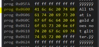
…In My Example Template I told .ORG to place this constant string at address 0x0300, but it is at exactly double that value. Atmel Debugger/Simulator simply does not display word addressing, even when looking at Program Space; as lovely as that would be. Thus, the address 0x0300, when used in the Code Segment is referring to the 0x0300th WORD in Program Space, which would be the 0x0600th byte; because a Word is 2 Bytes. Taking an Address and Logically Shifting it Left is equivalent to multiplying it by 2.
I divided my Code Section into 3 partitions. You would think they should go in sequential order, but I did not do that….
.CSEG .org 0x0800
    constantdata: .db "All that is gold does not glitter",0

.org 0x0000
    rjmp MAIN

//MAIN PROGRAM/////////
.org 0x0100
	COPYSTRINGPGM ramcopy,romdata

        //WRITE PROGRAM HERE....

	endloop:
		nop
		rjmp endloop
//PLACE SUBROUTINES HERE/////////////////////

.exit ///////////////////////////////////////
I started off with whatever address I want to store my constants at. If I don’t specify an address of my own, it will simply store my constants at either address 0, or wherever I declare them mid-code(which I can do). It doesn’t matter the exact address, I just usually want my constants kept away from actual Program Instructions while writing. Constants are technically written to Flash(ROM) before any instructions are executed, so chronologically, my line ordering can still make some sense. After declaring constants, my program is ready to begin. Code execution always begins at 0x0000. A very common thing to do is place a jmp instruction here and actually begin your program at a later address. This is because AVR devices often place interrupt vectors here, meaning in a complex program, the first bunch of addresses will probably be a table of jumps to different interrupt routines. So I like to save this space. I started my program at 0x0100, just because that was a nice clean number, far above any interrupt vectors. Of course, this program only copies a string from ROM to RAM, and then loops nothing forever. I always place an end loop as a catch for the end of my program. The program counter or instruction pointer should not be allowed to run astray at the end of the program. AFTER the endloop, is typically where I place my sub-routines. The endloop will protect these subroutines from being executed arbitrarily. Finally, the .EXIT directive marks the end of all code. You may freely write comments or keep notes in the lines below this directive and it will be ignored by the assembler.
